A project connecting large external AM band loop antennas to this radio is presented. Also, a techinque that can potentially fix poor sensitivity at the top end of the AM broadcast band is proposed.
The Eton Field BT radio is no longer sold. The Eton Elite Field Radio appears to be the successor to the Field BT. We have not examined the new Elite Field radio, but from the outside photos it appears identical to the Field BT radio. This project was developed for the Field BT radio and it may also work with the Elite Field model, but there's no guarantees on that.
We purchased one of these radios in 2018, mainly for use as an AM band receiver, and have been mostly pleased with it. Being interested in doing a little bit of searching for distant AM stations (often called AM DX'ing), it was soon realized that the internal ferrite rod antenna was less than optimal. This is not to say the internal antenna doesn't compare favorably with other table top radios -- it does. The issue is, no ferrite rod antenna of practical size will compare favorably with a large multi-turn air core loop or long wire antenna.
The first attempts at a better antenna involved building a couple of air-core loops. Each loop had an air-variable capacitor connected in parallel to permit resonating the loop at the intended receive frequency. Two methods of coupling these loops to the Field BT were tried.
Both of these ideas worked pretty well and allowed reception of much weaker signals. This approach can be a bit awkward because every time the station is changed, the air-variable capacitor must be adjusted for resonance at the new frequency.
Eventually, we couldn't help ourselves and started tearing into the Field BT just to see where that might lead. One interesting review by Jay Allen of the predecessor to the Field BT (the Field 550) here provided some very useful information. We learned that an integrated circuit manufactured by Silicon Labs (the Si4735) is the heart of this radio. The Si4735 is a one-chip multi-band receiver and all of the important receiver functions are contained therein. All indications are that both the Field 550 and Field BT use the same SiLabs chip.
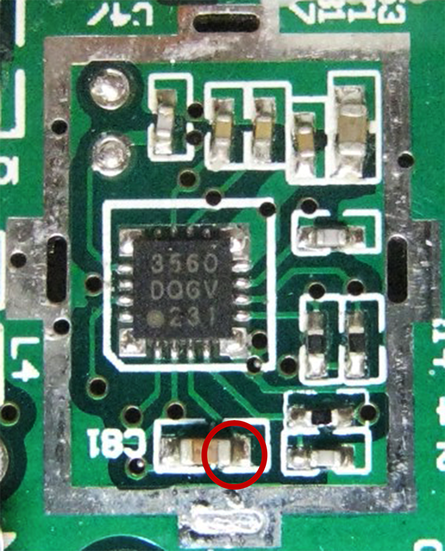
The image above is copied from Jay's review of the Field 550 and shows the Silicon Labs receiver IC. In the number 3560 on the package, 35 identifies the part as the Si4735, and 60 is the firmware revision. The date code on the last line probably refers to the 31st week in 2012 as manufacturing date. The red circle identifies the AM antenna input trace which is connected to one side of a DC blocking capacitor.
Four discoveries were made while poking around inside the Field BT.
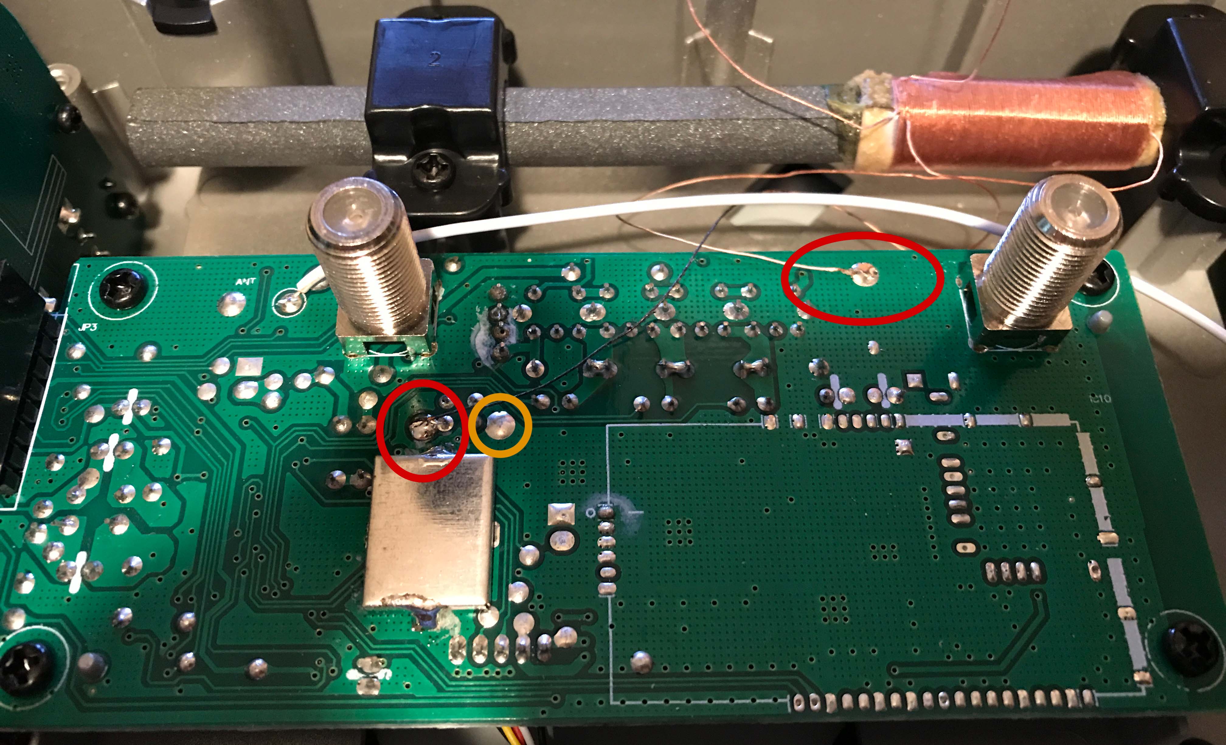
The image above shows some of these issues. Red circles identify where the main loop is connected to the RF board. The black wire connected just above the shield is the hot lead. The white wire is connected to ground way over on the other side of the board. This is less than ideal, as any noise developed in the ground plane between that point and where the black wire connects will be conducted directly into the radio's AM input. There is another ground pad, circled in orange which is where the AM loop ground wire probably should be connected.
Notice that the black wire (hot lead) passes near to, or over the top of two or three PCB traces. We don't know what signals are on those traces, but this is an opportunity for any digital or power supply noise that might be on them to couple into the receiver. The antenna leads should be kept away from RF board traces to avoid noise pickup. In fact this is almost impossible to accomplish because the rear panel design forces any wires between the two type-F connectors down close to the board when the rear panel is installed. This is discussed again later in the section on hacks.
The loop was un-soldered from the RF board and measured on a Hewlett-Packard HP4275A LCR meter. Inductance was found to be about 790uH. Measured losses started to pick up within the AM band1; the most likely cause is the ferrite material and we wonder if a little better performance would be had with a different material having lower losses in the AM band. Analysis of the LCR meter data provided an estimate of the effective parallel capacitance across the main loop, which is 1.52pF.
The inductance of 790uH is a potential problem when used with the Si4735 receiver. The radio chip likely contains an internal bank of capacitors and/or one or more varactors which can be switched in and out across the AM antenna. This allows the loop to be automatically resonated at different frequencies within the AM band. Information from the Si4735 data sheet and Silicon Labs' application note AN383 tells us that the minimum tuning capacitance across the IC's input terminals is 8pF. We also have the effective parallel capacitance of the main loop in parallel with that for a total of 9.52pF. Tuning the loop's 790uH inductance to resonance at the top of the AM band (1710kHz) requires a capacitance of 10.97pF. There's already capacitance of 9.52pF present at a minimum, which leaves headroom of 1.45pF. As a result, capacitance due to printed circuit board pads and traces, and wiring betwen PCB and main loop cannot exceed 1.45pF if the radio is going to tune all the way up to 1710kHz.
A limit of 1.45pF pretty small and it would be at least a challenge to meet this goal, if not downright impossible. We don't know if this is in fact a problem with the Field BT but suspect it likely is. If so, the symptom would be a reduction of sensitivity at the upper end of the AM band. A couple different fixes for this are discussed in the section on hacks below.1. Measured Q peaks with a value of 500 at 400kHz, and drops to 270 at 1MHz and 81 at 2MHz. Loss of Q due to skin effect would not increase this fast, so it is most likely due to ferrite losses.
Here we consider a couple of different modifications that can improve AM reception for the Field BT radio. The least intrusive modification provides a fix for the reduction in sensitivty at the top end of the AM band. This does presume there actually is a problem at the top end of the band, and we did not make any measurements to confirm that. You would need to at least strongly suspect this before considering the hack.
The main loop consists of 100 turns of Litz wire. One way to reduce the inductance is by simply removing a few turns from the coil. For example, we tried removing about 13 turns which got the measured inductance down to 600uH and increased the allotment for wiring and stray capacitance from 1.45pF to 4.92pF -- a much more reasonable number. This change also reduces the antenna's effective height by 13%, which is about a 1dB loss in sensitivity. That's not much to worry about if it fixes sensitivity problems at the top end of the band.
Taking it a bit further, removing 20 turns from the loop would only reduce sensitivity by about 2dB but would reduce inductance to about 500uH, providing 7.8pF of headroom for wiring and stray capacitance.
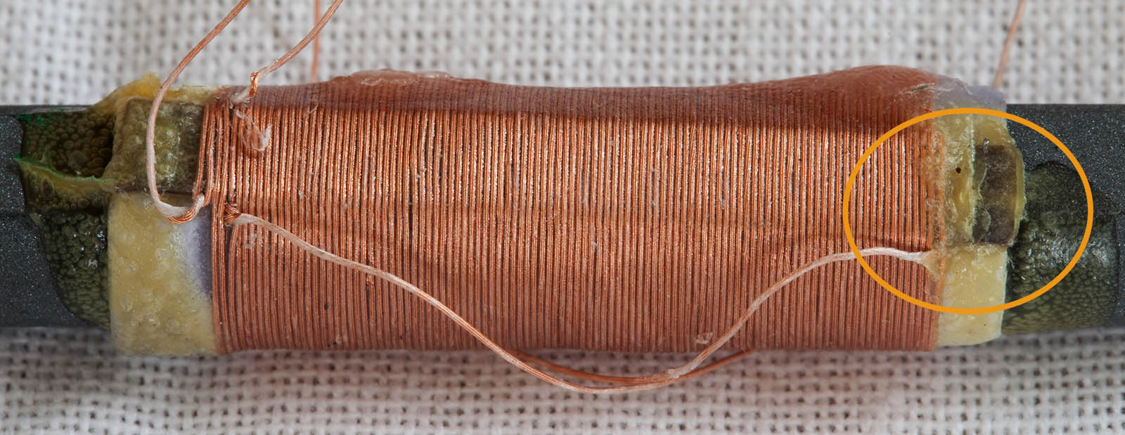
For those who wish to try this, a close up image of the main coil is shown above. The area circled in orange on the right is where we removed turns on our coil. The Litz wire disappears between the first two turns of the coil. From there, it goes under the cardboard spacer seen sticking out from under the coil. It pops out from under the spacer on the top side and the coil winding begins from there. To remove turns, the end of the wire must be pulled out from under the spacer. Start by picking away enough of the sticky gunk until the cardboard spacer can be pried up away from the coil form material. Once this is done, a pair of tweezers can be used to loosen the wire under the spacer and pull it out. The tinned end of the Litz wire may need to be cut off in order to pull it through under the cardboard spacer.
A more intrusive, but higher performance hack is to replace the ferrite loop with a large, external air core loop. This is eventually what we tried and it works extremely well. The sensitivity is the same or perhaps a bit better than using a magnetically coupled, resonant air core loop of the same size. This setup has the advantage that no external variable capacitor is required to resonate the loop -- the Si4735 does that automatically.
It was decided that the air core loop should provide at least a 10:1 (or 20dB) increase in loop voltage output compared to the original ferrite rod. The receiver does not display calibrated RSSI values so we are unable to measure the actual increase in sensitivity that was achieved. This is frustrating as the Si4735 radio chipc reports RSSI in units of dBuV, but the front panel display only shows "bars" for signal strength with five different levels.
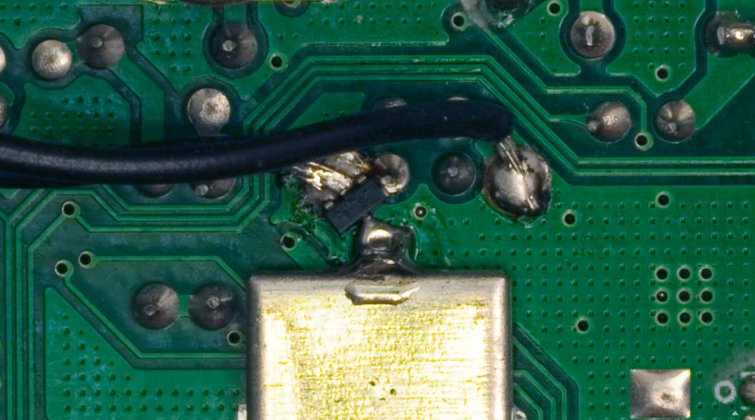
Not knowing if the Eton design includes static protection diodes across the ferrite loop, and knowing this is mandatory if connections are routed to the outside world, we added a pair of RF PIN diodes (Avago HSMP-2839) back-to-back across the AM input wire. These only add 0.6pF of extra capacitance and should not create a tuning problem at the top end of the band. The added diodes in a single SOT-23 package are shown in the photo below. Most of the component leads are buried in solder and not visible.
The way the radio case is designed, AM antenna wires are forced close to the PCB when the rear panel is installed. This is caused by the antenna connectors being recessed in the back panel. If the ferrite rod antenna is to be disconnected, and wires run directly to the rear panel AM antenna connector, additional issues arise. Without spot-gluing wires down to the PCB prior to assembly, it is hard to control exactly where they will end up after assembly. On top of this, there does not appear to be any routing option near the PCB that keeps the wiring entirely over the ground plane and away from PCB traces.
One way to reduce noise pickup from the PCB would be to twist both antenna wires together as they pass over the PCB, forcing any coupled noise to be mostly common-mode. Twisting the wires together adds a lot of capacitance however, so this is not really a good option.
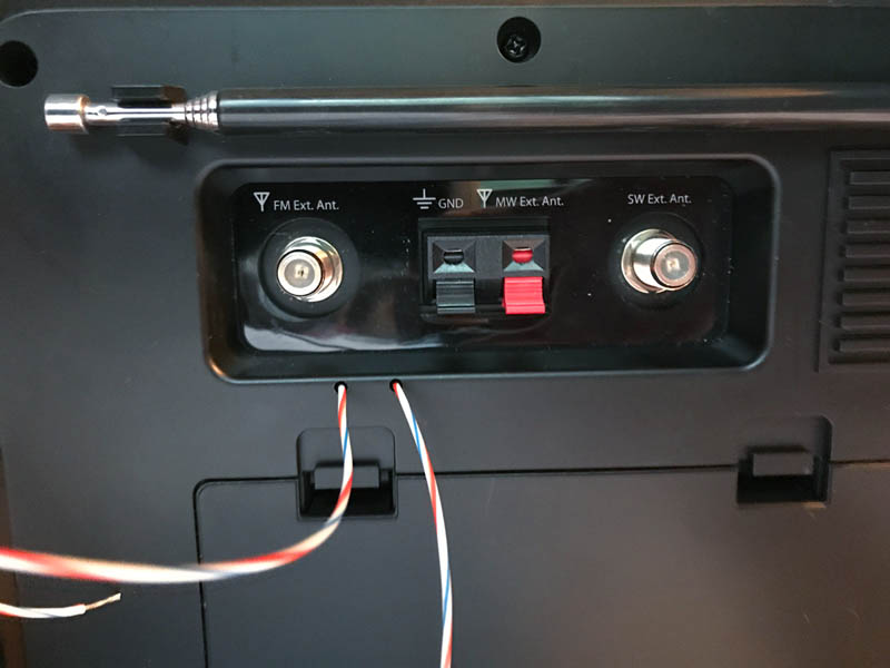
As shown above, our solution to this was to route the antenna wires immediately away from the PCB and out the back of the rear panel. This required drilling two small holes just below the recessed area, approximately aligned with the locations of antenna and ground pads on the PCB. During re-assembly, the wires are inserted through the two holes, and gently pulled tight as the rear panel is set in place. These wires can be captured in the existing AM antenna quick connector, or another terminal strip or quick connect can be attached to the outside of the rear panel. Tests with this wire routing confirm that noise pickup from internal sources is not an issue.
One of the ways in which electrically small antennas (such as ferrite rods and air-core loops) can be compared is through a parameter called effective height. The concept is simple; in the presence of an incoming radio signal (i.e. electro-magnetic plane wave) with known electric field strength, effective height tells us how much voltage will be induced in the antenna. For example, a radio signal with E-field of 1000uV/m impinging on an antenna with effective height of 0.1 meters will induce 1000uV/m times 0.1m or 100uV. For purposes here we don't need to worry about the actual voltages involved, but just the differences in effective height between antennas. Effective height allows a direct comparison of two different antennas, subject to certain limitations (discussed below). It varies with frequency, and is worst at the bottom end of the band (520kHz). The numbers presented below are computed at this frequency since it is worst case, although for comparisons between antennas we could use any frequency in the AM band -- the answer would be the same. A discussion of how to compute effective height for air and ferrite core antennas is beyond the scope of this article, and computed values are presented without further discussion.
The calculated effective height of the Field BT's ferrite rod antenna is 4.7mm (that's right -- millimeters). Not very big, is it? That's partly because these are non-resonant heights -- see below for more on that. The 48-inch octagonal loop we used as a replacement has an effective height of 107mm. It provides about 23 times more output voltage (27dB) to the receiver than the ferrite rod antenna. That's a pretty significant improvement.
One potential gotcha with comparing effective heights has to do with the fact these loops are operated at resonance. At resonance, the output voltage is multiplied by the loop's quality factor (a.k.a. Q). So in reality, if our ferrite antenna has an effective height of 4.7mm but is operated at resonance with a Q of 50, then the effective height is really 50 times 4.7mm or about 230mm. So if we're comparing two loop antennas operating at resonance with different Q values, that must be taken into account. As long as the Q is identical for two antennas, we can directly compare the non-resonant heights. If the air core loop also runs with a Q of 50, it will have an effective height of 5.3 meters.
Where does this Q value of 50 come from? Since the SiLabs data sheet does not specify the operating Q, we've had to guess. For an audio bandwidth of 5kHz, the AM signal bandwidth would be 10kHz. We've chosen this number due to AM broadcast frequency spacing of 10kHz. It's not clear what target bandwidth the radio chip is using, but this is our guess. Based on that, the maximum loop antenna Q at 500kHz would be 50.
Though the Q of these loops can be be measured, that doesn't solve the problem. Q is determined not only by the loop itself (inductance, RF resistance and ferrite losses, if any), but by resistance present at the receiver input. Silicon Labs' data sheet for the Si4375 tells us that a controlled resistance is intentionally connected inside the IC across the AM antenna input to manage resonated loop Q, but that's all we are told. What that resistance value is is a mystery. We have assumed that it is varied with the amount of capacitance added to resonate the loop, resulting in any loop being operated at the same Q value, regardless of inductance. Under this assumption, there's no need to make an adjustment for different operating Q values between different antennas. We further assume that each loop has a high enough inherent Q value that damping added by the receiver dominates the final value.
We note that the Field BT's ferrite antenna Q drops from 270 to 81 between 1MHz and 2MHz. The value at 2MHz is low enough that it might begin to have an noticeable effect on total resonant Q when connected to the Si4735. That's just a guess but it provides another possible explanation for reduced top-of-band sensitivity. This might be a reason to consider replacing the Field BT's internal ferrite rod with a different ferrite material. For example, using a 12x150mm rod of type 61 material with 80 turns of wire would get about 380uH of inductance and an effective height of 4.8mm at 540kHz. This is about the same height as the original antenna, but it would not exhibit the same drop in Q above 400kHz. As of May 2019 these are about $23US on Amazon and some may consider this a rather expensive option, as it might only provide a minor improvement in performance.
About the best possible performance available with an external ferrite would antenna would be to use either a 1/2 inch x 12-inch rod or two 1/2-inch x 7.5 rods joined tightly into a 15-inch long rod. The later would cost around $50-60US and could provide non-resonant effective heights as large as 10mm at 540kHz. It's still worth noting that the 48-inch octagonal air-core loop's effective height is 107mm and it costs a lot less money to build.
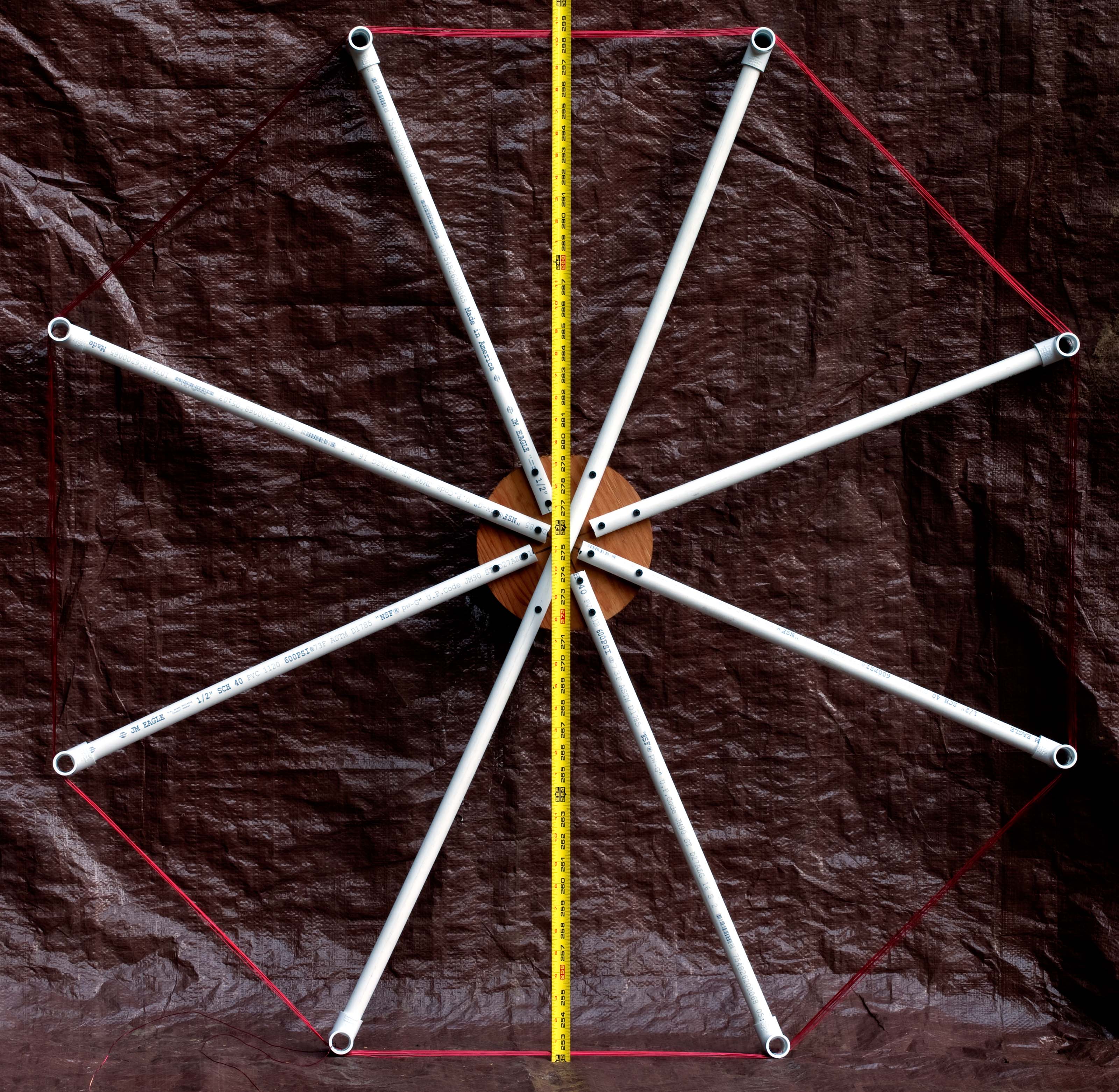
Physical parameters for the octagonal loop are shown below. Although the inductance is not very high, self resonance dropped too low in frequency if more than eight turns were used. The photo below shows the air core loop, build from half-inch PVC pipe attached to an 8-inch diameter plywood center with drywall screws. Notches were cut in the pipe tees with a dremel tool to space the wires at the desired interval.
| Octagonal Air Core Loop Specs | |
|---|---|
| Diameter at supports | 49 inches (1.26m) |
| Area | 1.187 sq meters |
| Turn count | 8 |
| Winding pitch | 6.35mm |
| Wire | 20ga magnet wire |
| Total wire length | 96 ft (29.3m) |
| Inductance | 209uH |
| Self resonance | 3.3MHz (estimated) |
| DC resistance | 1.20 ohms |
Right-click on photo and select "View Image", "Open Image" or similar to see larger (3200 x 3122 pixels) version.